9. Pipelined design
Table of Contents
- Pipeline is an important technique to increase the performance of a system.
- The basic idea is to overlap the processing of several tasks so that more tasks can be completed in the same amount of time.
9.1. Delay and throughput
Delay and throughput are the two criteria used to examine the performance of a system
- Delay: the time required to complete one task.
- Throughput: the number of tasks that can be completed per unit time.
Adding pipeline to a combinational circuit can increase the throughput but not reduce the delay.
9.2. Overview on pipelined design
The pipelining technique can be applied to a task that is processed in stages.
- An example: Pipelined laundry.
- A complete laundry includes the stages of washing, drying and folding, for example.

For non-pipelined process, a new load cannot start until the previous load is completed.
- It takes 240 minutes to complete the four loads.
- The delay of processing one load is 60 minutes.
- The throughput is 1/60 load per minute.

For pipelined process,
- It takes 120 minutes to complete the four loads.
- The delay in processing one load remains 60 minutes.
- The throughput increases to 2/60 load per minute.
- To process k loads, it will take 40+20k minutes.
- The throughput becomes k/(40+20k) load per minute -> 1/20 load per minute when k is large.
Pipelined combinational circuit
- A combinational circuit can be divided into stages so that the processing of different tasks can be overlapped.
- To ensure that the signals in each stage flow in the correct order and prevent any potential race, registers must be added between successive stages.
- The registers ensures that the signals can be passed to the next stage only at predetermined points.

Assume: propagation delay for each stage: T1, T2, T3 and T4. Tmax = max(T1, T2, T3, T4);
Thus, the minimum clock period has to accommodate the longest delay plus the overhead introduced by the buffer register in each stage: Tc = Tmax + Tr;
The effectiveness of the circuit
Propagation delay:
- non-pipelined circuit: T comb = T1+T2+T3+T4
- pipelined circuit: Tpipe = 4Tc = 4Tmax + 4Tr
Throughput:
- non-pipelined circuit: 1/T comb;
- pipelined circuit: k/(3Tc+kTc) -> 1/Tc.
Ideally, for an N-stage circuit
The propagation delay of each stage is identical (i.e., Tmax = Tcomb/N)
The register overhead (Tr) is comparably small
- T pipe = NTc = NTmax = T comb
- Throughput: 1/Tc = 1/Tmax = N/ T comb
Ideally, it is desirable to have more stages in the pipeline. However, when N becomes large,
- the propagation delay of each stage becomes smaller, but Tr remains the same; its effect cannot be ignored.
- In reality, it is difficult to keep dividing the original combinational circuit into smaller and smaller stages.
9.3. Adding pipeline to a combinational circuit
The candidate circuits for effective pipeline design should include the following characteristics:
- There is enough input data to feed the pipeline circuit.
- The throughput is the main performance criterion.
- The combinational circuit can be divided into stages with similar propagation delay.
- The propagation delay of a stage is much longer than the delay incurred due to the register.
The procedure to convert a combinational circuit to a pipelined design
- Derive the block diagram of the original combinational circuit and arrange it as a cascading chain.
- Identify the major components and estimate the relative propagation delays of these components.
- Divide the chain into stages of similar propagation delays.
- identify the signals that cross the boundary of the chain.
- Insert registers for these signals in the boundary.
Examples
Simple pipelined adder-based multiplier
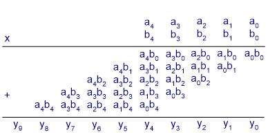
Non-pipelined multiplier in cascading stages
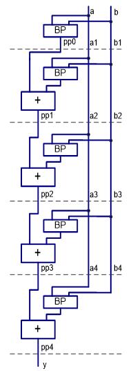
Non-pipelined circuit:
-- stage 2
pp2 <= pp1 + bp2;
-- stage 3
pp3 <= pp2 + bp3;
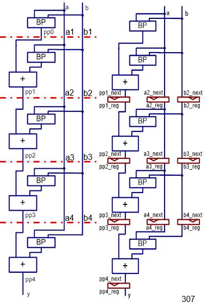
pipelined circuit:

-- register
if (reset = ‘1’) then
    pp2_reg <= (others => ‘0’);
    pp3_reg <= (others => ‘0’);
elsif (clk’event and clk=‘1’) then
    pp2_reg <= pp2_next;
    pp3_reg <= pp3_next;
end if;
…
-- stage 2
pp2_next <= pp1_reg + bp2;
-- stage 3
pp3_next <= pp2_reg + bp3;
Examples
Pipelined multiplier
More efficient Pipelined multiplier
- Use a smaller (n+1)-bit adder to replace the 2n-bit adder in an n-bit multiplier.
- Reduce the size of the partial-product register
- Reduce the size of the registers that hold the b signal.