1. Introduction
Table of Contents
1.1. Digital system design
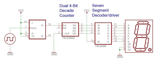
- Examples of Digital System: system level, or more accurately, register transfer level (RTL).

1.1.1. Abstraction
A key method of managing complexity is to describe a system in several levels of abstraction.
An abstraction is a simplified model of the system, showing only the selected features and ignoring the associated details.
- Transistor level
- Gate level
- Register transfer (RT) level
- Processor level
1.1.2. System Representation (View)
View: different perspectives of a system
1.1.2.1. Behavior view
- describe the functionalities and i/o behavior
- treat the system as a black box
1.1.2.2. Structural view
- describe the internal implementation (components and interconnections)
- essentially block diagram
1.1.2.3. Physical view
- add more info to structural view: component size, component location, routing wires
- e.g. layout of a printed circuit board
1.2. What is VHDL
1.2.1. VHSIC Hardware Description Language (VHDL)
- Very High-Speed Integrated Circuit program (VHSIC)
- A computer language for documenting and simulating circuits, and describing circuits for synthesis.
- A high level programming language with specialized constructs for modeling hardware.
1.2.2. History of VHDL
- Intermetrics, TI and IBM under US DoD contract 1983-1985: VHDL 7.2
- IEEE standardization: VHDL 1076-1987
- First synthesized chip, IBM 1988
- IEEE Restandardization: VHDL 1076-1993
- Minor change in standard 2000 and 2002
- VHDL standard IEEE 1076-2008 published in Jan 2009
1.2.3. The role of HDL
- Formal documentation
- Input to a simulator
- Input to a synthesizer

1.3. Basic VHDL concept
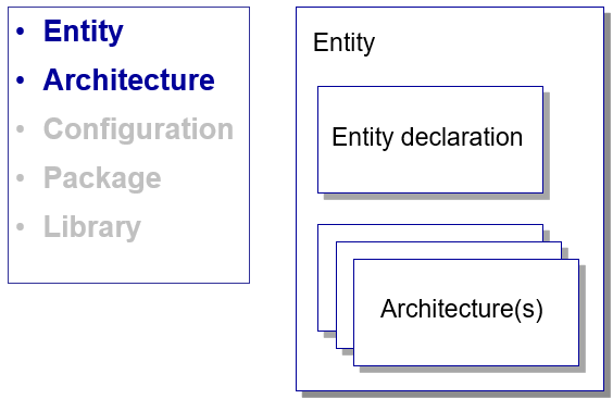
1.3.1. Entity
It defines an interface to a component
It names the entity, and
It describes the input and output ports that can be seen from the outside
- Mode of signals (i.e. in and out)
- Type of signals (i.e. bit)
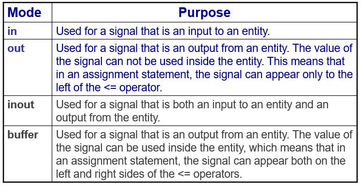
Possible modes for signals of entity ports
1.3.2. Architecture
- It defines the relationships between the inputs and outputs of a design entity.
- It consists of a declaration section followed by a collection of concurrent statements.
- It may be expressed in terms of behavior, data flow, or structure.
- It provides an “internal view” of a component.
Examples
NAND2 Gate


S <= A and B;
C <= not S;
C <= not S;
S <= A and B;
These two codes will produce the same result.
Architecture:Behavior style
architecture BEHAVIOR  of NAND2 is
begin
     process (A,B) is
     begin
         if (A=‘1’ and B=‘1’) then
                C <= ‘0’;
         else
            if (A=‘0’ and B=‘0’) or (A=‘0’ and B=‘1’)
                or (A=‘1’ and B=‘0’) then
                    C <= ‘1’;
            end if;
         end if;
     end process;
end architecture BEHAVIOR;