8. Parameterized Design
Table of Contents
Goal: Design reuse
- Ideally, we want to design some common modules that can be shared by many applications.
- Since every application is different, it is desirable that a module can be customized to some degree to meet the specific need of an application.
- Customization is normally specified by explicit or implicit parameters
Width Parameters
- The widths of data signals normally can be modified to meet different requirement.
- The width parameters of a parameterized design specify the sizes (i.e., number of bits) of the relevant data signal.
Feature Parameters
- Specify the structure or organization of a design.
- Defined on an ad hoc basis.
- To include or exclude certain functionalities (i.e., features) from implementation or to select one particular version of the implementation
8.1. Generics
The generic construct of VHDL is a mechanism to pass information into an entity and a component.
- They are first declared in entity and component declaration and later assigned a value during component instantiation
entity para_binary_counter is
    generic (WIDTH: natural);
    port (
       clk, reset: in  std_logic;
      q: out  std_logic_vector(WIDTH-1 downto 0)
    );
end entity para_binary_counter;
After the declaration, the generic can be used in the associated architecture bodies.
A generic cannot be modified inside the architecture body and thus functions like a constant
- It is sometimes referred to as a generic constant.
architecture arch of para_binary_counter is
    signal reg, reg_next : std_logic_vector (WIDTH-1 downto 0);
begin
    process (clk, reset) is
    begin
          if reset = ‘1’ then
            reg <= (others =>’0’);
          elsif clk’event and clk=‘1’ then
        reg <= reg_next;
          end if;
    end process;
-- next-state logic
    reg_next <= reg + 1;
    q <= std_logic_vector(reg);
end architecture arch;
- To use the parameterized free-running binary counter in a hierarchical design, a similar component declaration should be included in the architecture declaration.
- The generic can then be assigned a value in the generic mapping section when a component instance is instantiated.
- Example of the use of generics

Parameterized reduced-xor circuit using a generic
8.2. Array attribute
A VHDL attribute provides information about a named item, such as a data type or a signal.
We have used the ’event attribute, as in clk’event, express the changing edge of the clk signal.
A set of attributes is associated with an object of an array data type. Let s be a signal with an array data type.
- s’left, s’right: the left and right bounds of the index range of s.
- s’low, s’high: the lower and upper bounds of the index range of s.
- s’length: the length of the index range of s.
- s’range: the index range of s.
- s’reverse_range: the reversed index range of s.
The attributes can be applied to the signal defined with std_logic_vector, unsigned and signed:
signal s1: std_logic_vector (31 downto 0);
signal s2: std_logic_vector (8 to 15);

Parameterized reduced-xor circuit using an attribute
The range of the for loop can also be expressed as:
- for i in a’low+1 to a’high loop
- for i in a’right+1 to a’left loop
The last signal assignment
y <= tmp (tmp’left);
8.3. Unconstrained Array
- Unconstrained array is defined as an array type with specified data type of the index value, but without specified exact bounds of the index value.
- Example:
type std_logic_vector is array (natural range <>) of std_logic - Similarly, we have unsigned and signed data types.
- If an object is declared with an unconstrained array data type, we must specify its index range when the data type is used, as 15 downto 0 in
signal x: std_logic_vector(15 downto 0); - A special case: the unconstrained array can be declared without specifying the range in port declaration.
- Example:
- Since no range is specified for d and q, the boundaries of the two signal will not be check in the analysis stage.
Parameterized reduced-xor circuit using an unconstrained array
The code appears to be correct at first glance
- If we map the a signal to an actual signal with the type of std_logic_vector of 8 bits during component instantiation, we may have a to be:
std_logic_vector(7 downto 0);
std_logic_vector(0 to 7);
std_logic_vector(15 downto 8);
std_logic_vector(8 to 15);
- The code does not work properly for the last two formats.
Improved parameterized reduced-xor circuit using an unconstrained array
8.4. Comparison
The unconstrained array mechanism uses attributes to infer the relevant information from the actual signal.
- More general and flexible than the generic mechanism, but also
- More opportunities for errors.
- Requires comprehensive error-checking code
Generic mechanism is preferred, unless a module is extremely general and widely used.
- More rigid
- It clearly specifies the range, direction and width of each signal and avoids many subtle erroneous conditions.
8.5. Generate Statement
The generate statements are concurrent statements with embedded internal concurrent statement, which can be interpreted as a circuit part.
Two types of generated statements:
- for generate statement: used to create a circuit by replicating the hardware part
- conditional or if generate statement: used to specify whether or not to create an optional hardware part.
8.5.1. For Generate Statement
- Many digital circuits can be implemented as a repetitive composition of basic building blocks, exhibiting a regular structure, such as a one-dimensional cascading chain, a tree-shaped connection or a two-dimensional mesh.
- For generate statement syntax
gen_label:  -- mandatory to identify to this    -- particular generate statement
    for loop_index in loop_range generate
          concurrent statements;                             -- describe a stage of the iterative circuit
    end generate;
- The loop_range has to be static. It is normally specified by the width parameters.
Examples
Binary decoder
- A binary n-to- 2 n decoder is circuit that asserts one of the 2 n possible output signal according to an n bit input signal.
- One way to view the binary decoder is to treat each bit of the decoded output as the result of a constant comparator.

Parameterized binary decoder using a for generate statement

Parameterized reduced-xor circuit using a for generate statement
architecture gen_linear_arch of reduced_xor is
    signal tmp: std_logic_vector(WIDTH-1 downto 0);
begin
    tmp(0) <= a(0);
    xor_gen:
          for i in 1 to (WIDTH-1) generate
        tmp(i) <= a(i) xor tmp(i-1);
          end generate;
     y <= tmp(WIDTH-1);
end architecture gen_linear_arch;
- In an iterative structure, the boundary stages interface to the external input and output signals, and sometimes their connections are different from the regular blocks.
8.5.2. Conditional Generate Statement
- The conditional generate statement is used to specify an optional circuit that can be included or excluded in the final implementation.
- Conditional generate statement syntax
    gen_label:      -- mandatory
    if boolean_exp generate -- boolean_exp must be static
          concurrent statements;
end generate;
- There is no else branch in conditional generate statement.
- If we want to include one of the two possible circuits in an implementation, we must use two separate if generate statements.
Reduced-xor circuit revisited
- One common use of the conditional generate statement is to describe the “irregular” stages in a for generate statement.
- For example, two statements
tmp(0) <= a(0); y <= tmp(WIDTH-1);are used to rename the input and output signals in the for generate statement examples. - To eliminate these statements, we can use conditional generate statements inside the for generate statement.
Parameterized reduced-xor circuit with a conditional generate statement
Examples
Up-or-down free-running binary counter
- An up-or-down binary counter is a counter that can be instantiated in a specific mode.
- Note that the “or” here means that only one mode of operation, either counting up or counting down but not both, can be implemented in the final circuit.
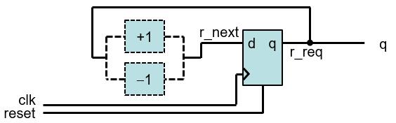
- We use the UP generic as the feature parameter to specify the desired mode.
Up-or-down free-running binary counter
Up-and-down free-running binary counter
Counter with an optional output buffer
- An output buffer can remove glitches from the signal.
- Since the buffer is only needed for certain application, it will be convenient to include the buffer as an optional part of the circuit.
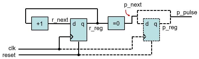
Counter with an optional output buffer
8.6. Comparison
To create a circuit with a selectable feature:
- use conditional generate statement
- a full-featured circuit with some input control signal connected to constant values to permanently enable the desired feature
- use the configuration construct
Assume we need a 16-bit up counter in a design.
count16up: up_or_down_counter
      generic map (WIDTH => 16, UP =>1)
      port map (clk => clk, reset => reset, q=>q);
count16up: up_and_down_counter
      generic map (WIDTH => 16)
      port map (clk => clk, reset => reset, mode => ‘1’, q=>q);
Difference
The up-or-down counter instance
- creates a circuit with only the needed features.
- The selected portion of code is passed to the synthesis stage, i.e., the synthesis software only needs to synthesize the selected portion.
The up-and-down counter instance
- creates a circuit that consists of all features and uses an external control signal to selectively enable a portion of the circuit.
- The entire VHDL code is passed to synthesis stage. The synthesis software eliminates the unused portion through logic optimization.
In general, use of the feature parameters and conditional generate statement is better than the full-featured approach.
The selected hardware creation can also be achieved by configuration where multiple architecture bodies are constructed, each containing a specific feature, e.g., architectures up_arch and down_arch of the same entity updown_counter, for counting up and counting down, respectively.
And the following instantiation can be used to select the counting up circuit.
count16up: work.updown_counter(up_arch)
          generic map(WIDTH =>16)
          port map (clk => clk, reset => reset, q => q);
Up-or-down counter with two architecture bodies
Conversely, we can merge the logic from several architecture bodies into a single body and use a feature generic and conditional generate conditions to select the desired portion.
There is no rule about when to use a feature parameter and when to use a configuration construct. In general,
- code with a feature parameter is more difficult to develop and comprehend, but on the other hand, if we use a separate architecture body for each distinctive feature, the number of architecture bodies will grow exponentially and becomes difficult to manage.
- when a feature parameter leads to significant modification or addition of the no-feature codes and starts to make the code incomprehensible, it is probably a good idea to use separate architecture bodies and the configuration construct.
8.7. For Loop Statement
- The for loop statement is a sequential statement and is the only sequential loop construct that can be synthesized.
for index in loop_range loop    --loop_range must be static
      sequential statements;
end loop;
- The basic way to synthesize a for loop statement is to unroll or flatten the loop. Unrolling a loop means to replace the loop structure by explicitly listing all iterations.
Examples
Binary decoder
The code is very similar to the for generate version
architecture loop_arch of bin_decoder is
begin
    process (a)
    begin
          for i in 0 to (2**WIDTH-1) loop
if i = to_integer(unsigned(a)) then code(i) <= ‘1’;
        else code(i) <= ‘0’;
        end if;
          end loop;
      end process;
end architecture gen_arch;
Examples
Reduced-xor circuit
For loop version: For generate version:
Examples
Priority Encoder
- Recall that a signal can be assigned with multiple times inside process and only the last assignment takes effect.
- A priority encoder is a circuit that returns the binary code of the highest-priority request.
- Assume that the input is an array of r(WIDTH-1 downto 0), and r(WIDTH-1) has the highest priority.
8.8. Comparison
Both the for generate and for loop statements are used to describe replicated structures.
For generate statement:
- can only use concurrent statements.
- start a design with a conceptual diagram of a few stages; the diagram is used to identify the basic building block and connection pattern, and then the code of the loop body is derived.
For loop statement:
- can only use sequential statements.
- the body of the loop statement can be more general and versatile.
- may lead to unnecessarily complex implementation or even an unsynthesizable description.