3. Concurrent statement
Table of Contents
The operation of digital system is inherently concurrent.
Within VHDL signals are assigned values using signal assignment statements.
sum <= (x xor y) after 5 nsMultiple signal assignment statements are executed concurrently in simulated time and are referred to as concurrent signal assignment statements (CSAs).
There are several forms of CSA statements:
- Simple CSA
- Conditional signal assignment
- Selected Signal assignment
3.1. Simple CSA
architecture concurrent_behavior of half_adder is
begin
    sum <= ( x xor y) after 5 ns;
    carry <= (x and y) after 5 ns;
end architecture concurrent_behavior;
- General form:
target <= expression; - expression is logical, comparative or arithmetic operations.
- General form:
- The execution of the statements is determined by the flow of signal, rather than textual order.
Examples
Half_adder


library IEEE;
use IEEE.std_logic_1164.all;
entity half_adder is
port (x, y : in std_logic;
        sum, carry : out std_logic);
end entity half_adder;

architecture concurrent_behavior of half_adder is
begin
    sum <= ( x xor y) after 5 ns;
    carry <= (x and y) after 5 ns;
end architecture concurrent_behavior;
Examples
Full_adder


library IEEE;
use IEEE.std_logic_1164.all;
entity full_adder is
port (A, B, Cin : in std_logic;
        Sum, Cout: out std_logic);
end entity full_adder;
architecture dataflow of full_adder is
    signal s1, s2, s3 : std_logic;
    constant gate_delay : time := 10 ns;
begin
    L1: s1 <= (A xor B) after gate_delay;
    L2: s2 <= (Cin and s1) after gate_delay;
    L3: s3 <= (A and B) after gate_delay;
    L4: sum <= (s1 xor Cin) after gate_delay;
    L5: cout <= (s2 or s3) after gate_delay;
end architecture dataflow;
L1: s1 <= (A xor B) after gate_delay;
L2: s2 <= (Cin and s1) after gate_delay;
L3: s3 <= (A and B) after gate_delay;
L4: sum <= (s1 xor Cin) after gate_delay;
L5: cout <= (s2 or s3) after gate_delay;
3.2. Conditional signal assignment
- Simple CSAs is convenient for describing gate-level circuits whose behavior can be expressed with Boolean equations.
- It is useful to model circuits at higher levels of abstraction such as multiplexors and decoders.
Examples
4-to-1, 8-bit multiplexor

library IEEE;
use IEEE.std_logic_1164.all;
entity mux4 is
port (In0, In1, In2, In3 : in std_logic_vector (7 downto 0);
        S: in std_logic_vector(1 downto 0);
        Z : out std_logic_vector (7 downto 0) );
end entity mux4;
architecture con_arch1 of mux4 is
begin
    Z <=In0 when S = “00” else
        In1 when S = “01” else
        In2 when S = “10” else
        In3;
end architecture con_arch1;
architecture con_arch2 of mux4 is
begin
Z <= In0 when S = “00” else
     In1 when S = “01” else
     In2 when S = “10” else
     In3 when S = “11” else
     “XXXXXXXX”;
end architecture con_arch2;
- The conditional signal assignment itself is a concurrent signal assignment.
- It has one target, but can have more than one expression.
- When this CSA is executed, the expressions in the right hand side are evaluated in the order that they appear.
- The order of the expressions with their respective conditions inside the statement is important.
- Even there are several lines of text, this corresponds to only one signal assignment statement.
Examples
4-to-2 priority encoder
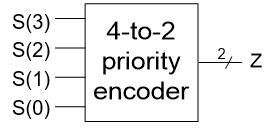
Assume that S(3) has the highest priority
library IEEE;
use IEEE.std_logic_1164.all;
entity pr_encoder is
port (S: in std_logic_vector(3 downto 0);
        Z : out std_logic_vector (1 downto 0) );
end entity pr_encoder;
architecture con_behavioral of pr_encoder is
begin
    Z <=“11” when S(3) = ‘1’ else
        “10” when S(2) = ‘1’ else
        “01” when S(1) = ‘1’ else
        “00” when S(0) = ‘1’ else
        “00”;
end architecture con_behavioral;
3.3. Selected signal assignment
- It is similar to the conditional signal assignment statement.
- The value of a target signal is determined by the value of a select expression.
Examples
the same 4-1 multiplexer.
architecture sel_behavioral of mux4 is
begin
    with S select
        Z <= In0 when “00”,
             In1 when “01”,
             In2 when “10”,
             In3 when others;
end architecture sel_behavioral;

Examples
4-to-2 priority encoder based on a selected signal assignment statement


architecture sel_arch of pr_encoder is
begin
    with S select
        Z <= “11” when “1000” | “1001” | “1010” | “1011” |
                             “1100” | “1101” | “1110” | “1111”,
             “10” when “0100” | “0101” | “0110” | “0111”,
             “01” when “0010” | “0011”,
             “00” when others;
end architecture behavioral

architecture sel_arch of pr_encoder is
begin
    with S select
        Z <= “11” when “1---”,
             “10” when “01--”,
             “01” when “001-”,
             “00” when others;
end architecture behavioral
- The choices for the select expression are not evaluated in sequence.
- All choices are evaluated, but one and only one must be true.
- All of the choices that the programmer specifies must cover all the possible values of the select expression.
- When an event occurs on a signal used in the select expression, or any of the signals used in one of the choices, the statement is executed.
3.4. Understanding delays
Accurate representation of the behavior of digital circuits requires accurate modeling of delays through the various components.
Three types of delay models
- Inertial delay model
- Transport delay model
- Delta delay
3.4.1. The inertial delay model
- Digital circuits takes a finite amount of time for the output of a gate to respond to a change on the input.
- This implies that the change on the input has to persist for a certain period of time to ensure that the output will response.
- If it does not persist long enough the input events will not be propagated to the output.
- This propagation delay model is referred to as the inertial delay model.
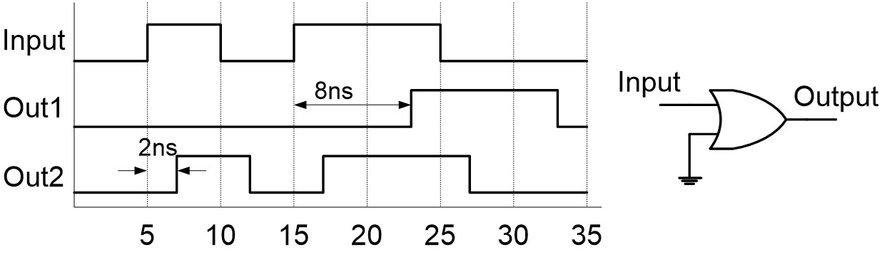
Out1 <= Input or ‘0’ after 8 ns;
Out2 <= Input or ‘0’ after 2 ns;
- Any pulse in the input with a width of less than the propagation delay through the gate is said to be rejected.
- often used for component delays
- Default in VHDL program
3.4.2. The transport delay model
Transport delay models the delays in hardware that do not exhibit any inertial delay. This delay represents pure propagation delay; that is, any changes on an input are transported to the output, no matter how small of the width, after the specified delay. Keyword transport is used in a signal assignment statement for transport delay model.

Out1 <= transport (Input or ‘0’) after 8 ns;
Out2 <= transport (Input or ‘0’) after 2 ns;
- Pulses are propagated, irrespective of width
- good for interconnect delays.
3.4.3. Delta Delays
- If we do not specify a delay for the occurrence of an event on a signal, for example
sum <= (x xor y);a delta delay is assumed by the simulator - Delta delay is an infinitesimally small delay.
- In a signal assignment, the value is not assigned to the signal directly but after a delta delay at the earliest.
- Delta delays are simply used to enforce dependencies between events and thereby ensure correct simulation.
Examples
combinational

library IEEE;
use IEEE.std_logic_1164.all;
entity combinational is
port (In1, In2 : in std_logic;
        z : out std_logic);
end entity combinational;

architecture behavior of combinational is
     signal s1, s2, s3, s4 : std_logic := 0;
begin
     s1 <= not In1;
     s2 <= not In2;
     s3 <= not (s1 and In2);
     s4 <= not (s2 and In1);
     z <= not (s3 and s4);
end architecture behavior;
