7. Modeling at the FSMD level
Table of Contents
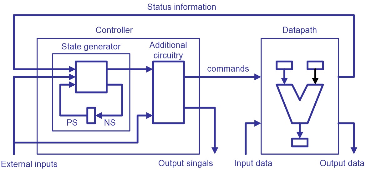
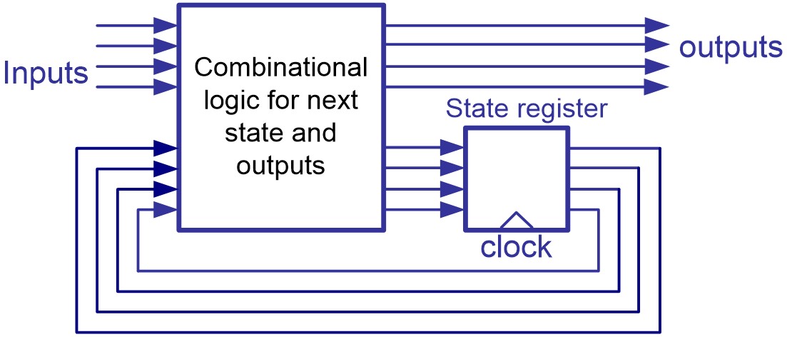
- A digital design is conceptually divided into two parts – a controller and a datapath.
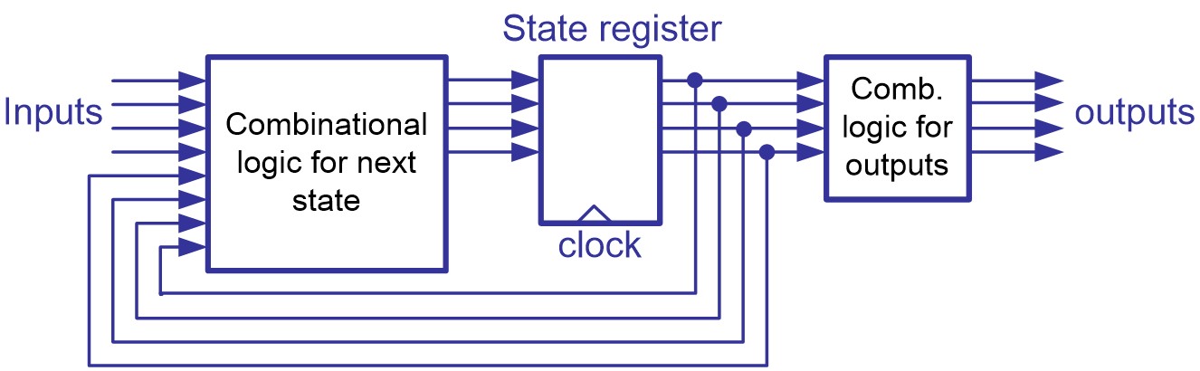
- A sequential circuit which is implemented in a fixed number of possible states is called a finite state machine (FSM).
It contains five elements:
- symbolic state
- input signal
- output signal
- present state
- next state
Two types of FSM:
- Moore machines
- Mealy machines
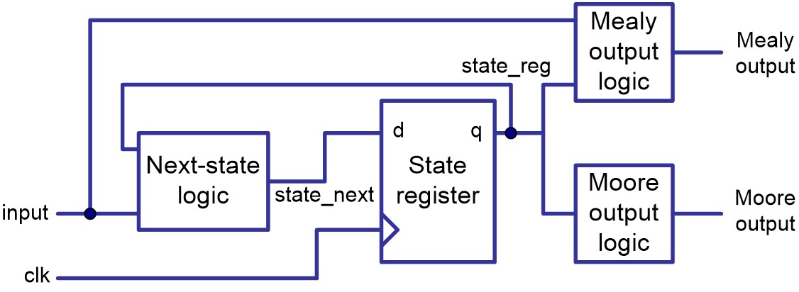
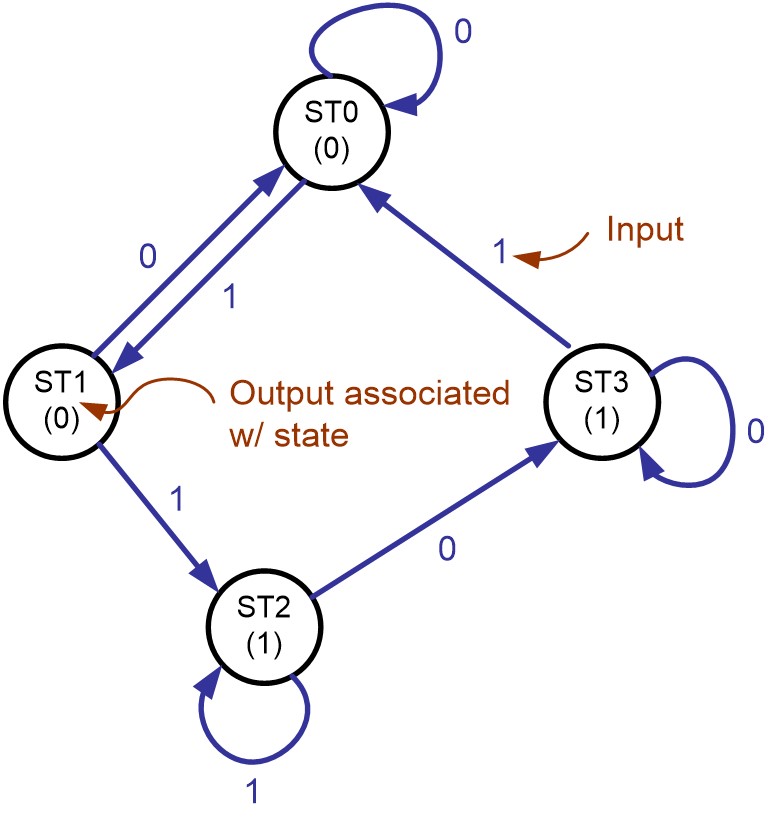
7.1. Moore machine
In the Moore modal of sequential circuits, the outputs are the functions of the present state only.
Examples
A state transition diagram of a Moore machine
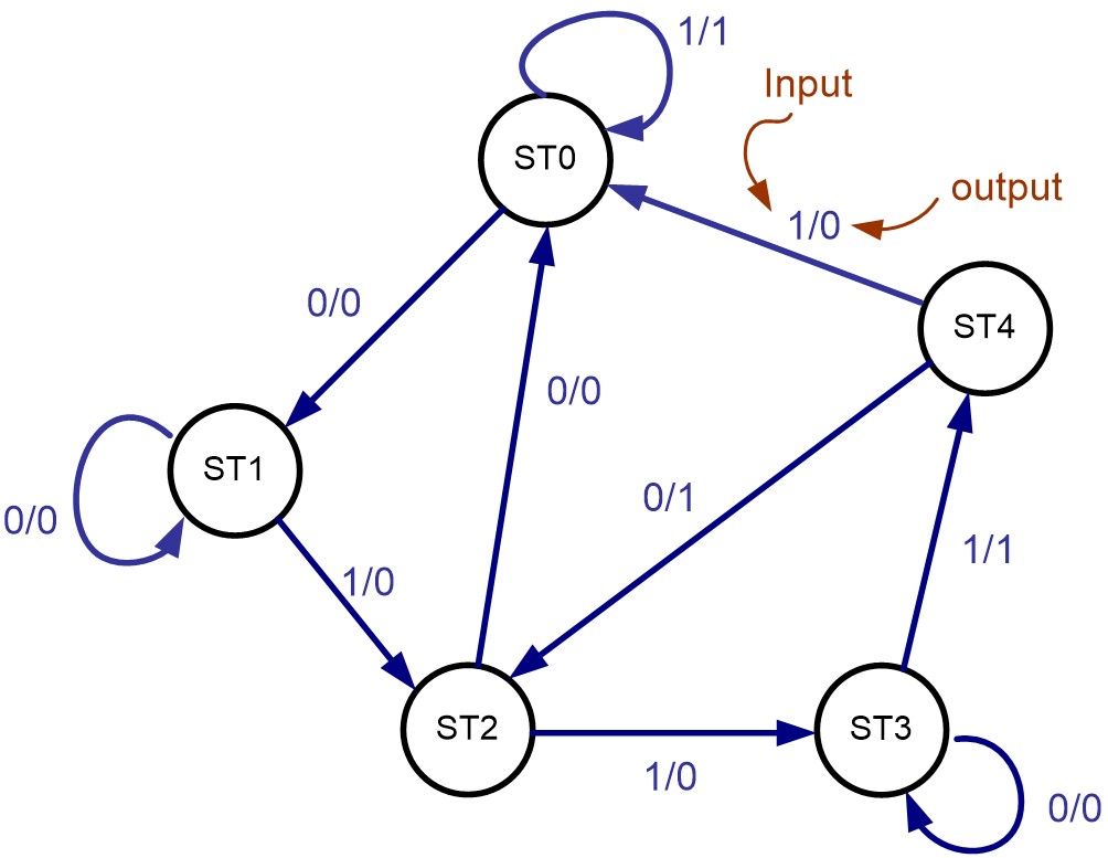
7.2. Mealy machine
In the Mealy modal, the outputs are the functions of both the present state and current inputs.
Examples
A state transition diagram of a Mealy machine
7.3. An FSM with a datapath (FSMD)
A traditional FSM
- cannot represent storage elements (register) except the state registers.
- works well for a design with a few to several hundred states.
An FSM with a datapath (FSMD) is an extension of a traditional FSM.
- storage and signals can be declared.
- Within a state expression, comparison, arithmetic or logic operations on these signals can be performed.
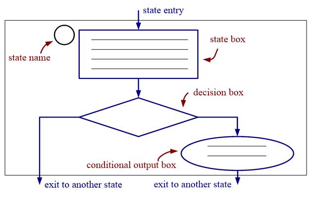
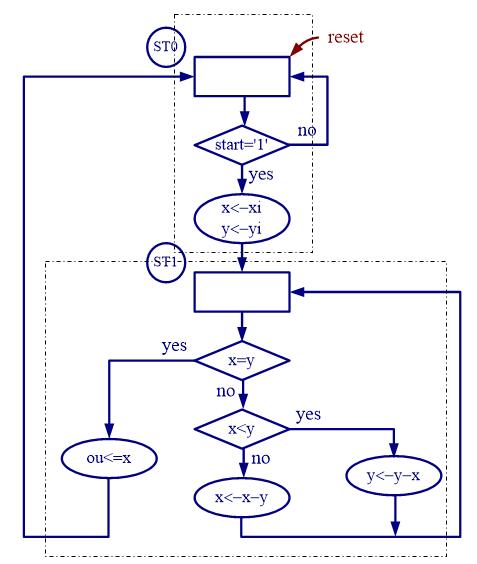
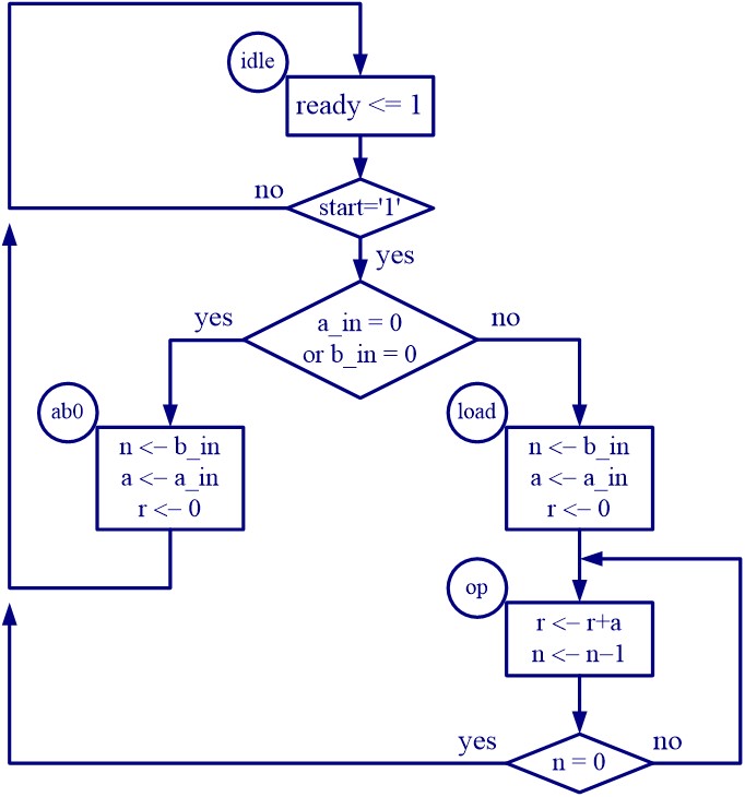
Algorithm state machine (ASM) chart
The behavior of a FSMD can be represented as a flow-chart-like description – algorithm state machine (ASM) chart.
ASM chart is constructed from ASM blocks;
An ASM block consists of three basic elements:
- the state box
- the decision box
- the conditional output box.
Examples
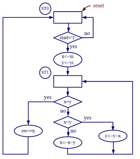
find the greatest common divisor of two eight-bit numbers xi and yi
    x = xi;
    y= yi;
St1:
If x=y then
          ou=x;
    Else {
          if x> y then x = x-y;
          Else y= y-x;
          Go to st1;
    }
Examples
GCD calculator
Examples
find the greatest common divisor of two eight-bit numbers xi and yi
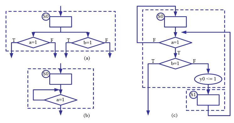
Rules to Construct ASM Chart:
- For a given input combination, there is one unique exit path from the current AMS block.
- The exit path of an ASM block must always lead to a state box. The state box can be the state box of the current ASM block or a state box of another ASM block.
Common errors in ASM Chart Construction
Examples
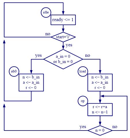
FSMD design of a repetitive-addition multiplier
Consider a multiplier with a_in and b_in, and with output r_out. The repetitive-addition algorithm can be formalized in the following pseudo-code:
if (a_in =0 or b_in =0) then{
    r = 0;}
else{
    a = a_in;       n = b_in;  r = 0;
    r = r + a;
    n = n - 1;
    if (n = 0) then {goto stop;}
    else {goto op;}
}
r_out = r;
Step 1: Defining the input and output signals
Input signals:
- a_in and b_in: input operands. 8-bit signals with std_logic_vector data type and interpreted as unsigned integers
- start: command. The multiplier starts operation when the start signal is activated.
- clk: system clock;
- reset: asynchronous reset signal for system initialization.
Output signals
- r_out: the product. 16-bit signals.
- ready: external status signal. It is asserted when the multiplication circuit is idle and ready to accept new inputs.
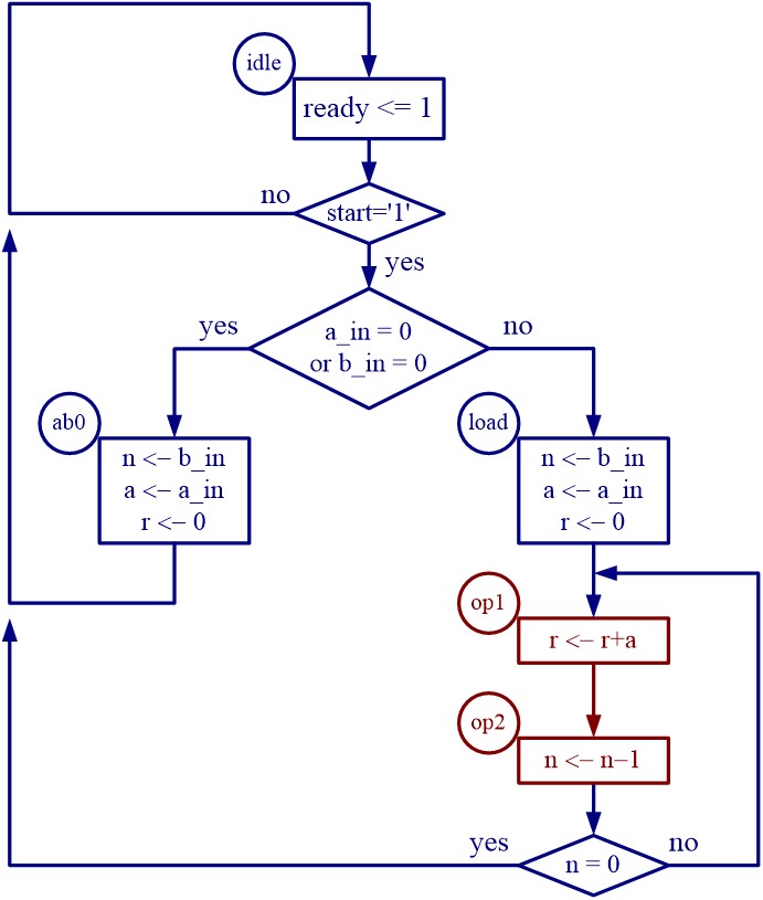
Step 2: Converting the algorithm to an ASM chart
Step 3: Constructing the FSMD
Basic data path can be constructed as follows:
- List all possible RT operations in the ASM chart.
- Group RT operations according to their destination registers.
- Derive the circuit for each group RT operation.
- Add the necessary circuits to generate the status signals.
3.1 The circuit require 3 registers, to store signals r, n, and a respectively.
3.2. The RT operations:
- RT operation with the r register:
- r <- r ( in the idle state)
- r <- 0 (in the load and ab0 state)
- r <- r + a ( in the op state)
- RT operation with the r register:
- RT operation with the n register:
- n <- n ( in the idle state)
- n <- b_in (in the load and ab0 state)
- n <- n - 1 ( in the op state)
- RT operation with the n register:
- RT operation with the a register:
- a <- a ( in the idle and op state)
- a <- a_in (in the load and ab0 state)
- RT operation with the a register:
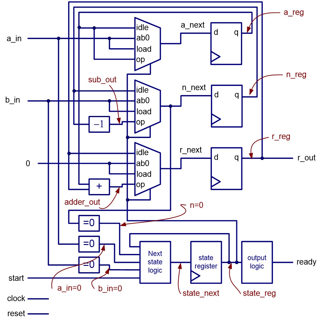
- Step 4: VHDL descriptions of FSMD
Resource sharing via FSMD example of repetitive-addition multiplier
- Many RT operations perform the same or similar function.
- Some function unit can be shared as long as these operations are scheduled in different states.
- the 16-bit adder and 8-bit decrementor are shared in the following example.
Modified ASM chart


sharing on a repetitive-addition multiplier